
Topics Included
- Included in your SureCam package
- Mounting your camera
- Mounting and Connecting the Combined Antenna
- Cable Routing
- Wiring
- (Optional) Using the View Monitor for video quality check
- Device Calibration
- Remote Video Quality Check
Installation Breakdown:
Included in your SureCam package:
Your SureCam kit comes with the following items:
- 1 x SureCam road-facing camera
- Mounts included:
-
- Universal Mount
-
- 1 x Combined antenna (GPS + Cellular) with double-sided tape (separate)
- 1 x Power cable / wiring harness
- 2 x inline fuses (red for constant, black for ignition) with holders
- 1 x Alcohol wipe
Tools needed for install:
The following tools are required but not included in your SureCam kit:
- A multimeter
- Insulated crimping tools
- Trim removal tools
- Cable ties
- A range of socket wrenches
- A set of Torx bits and Hex keys OR a set of Allen wrenches
- Electrical tape
- Measuring tape
- Assorted screwdrivers
- View Monitor (optional) - Please purchase the following if you would like to verify the video quality during the install process:
-
- Truck Dash Mounting Monitor: Amazon purchase link here
- RG58 RCA Male to Fakra Z Female: Amazon purchase link here
- Cigarette Lighter Power Plug Cable Adapter: Amazon purchase link here
-
Mounting your camera
Introduction to road-facing camera mounts
Each SureCam device ships with a universal mount, shown below.
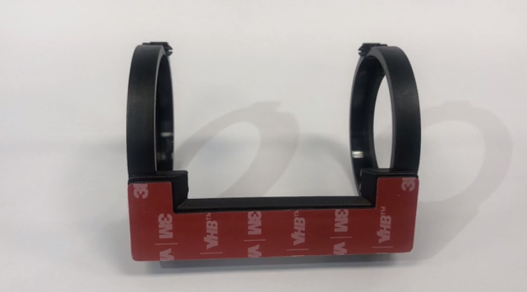
The mount is equipped with high-quality, self-adhesive black tape on both the bottom and sides of the shield. This ensures that the camera will stay securely in place during travel.
Where to place the mount
Be sure that the windshield area is free of dirt and debris, and that the camera is not obstructing the driver's view of the road. Make a note of the desired location of the mount.
CAUTION: Do not attach the mount at this point.
- Note: For federal guidelines regarding camera mounting, see here.
- Note: For vehicles with larger hoods (Peterbilts, Kenworths etc.), the best place to place the mount is in the upper center portion of the windshield. For vehicles with exterior sun visors, please consider the positioning of the camera to avoid any obstruction to its view.
Preparing the windshield before mounting
Note: If the ambient temperature is below 71° F or 21° C, ensure that the windshield is heated to this level before starting preparation. You can accomplish this by running the front defrosters.
CAUTION: You should always wipe down the selected portion of the windshield using the alcohol wipe provided, before adhering the mount. The area must be clean and free of any smudges or debris before attaching the mount. Missing this step could result in mount failure.
Placing the road-facing camera mount
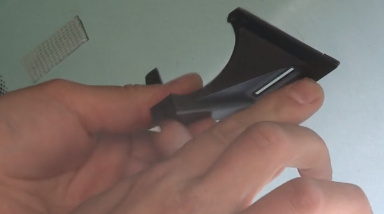
- Before removing the adhesive tape, place the mount in the desired position on the windshield with the wide portion of the mount facing downward. Be sure that the mount is level, and note the desired location.
- Next, remove the adhesive tape from the underside of the mount and prepare to adhere to the windshield.
- With the wide portion of the mount facing downward (see below), press the mount to the windshield firmly for at least 10 seconds.
Mounting the road-facing camera
CAUTION: Before mounting the camera, be sure the vehicle ignition is completely turned off and the camera is not plugged into power.
- Start by placing the camera into the mount and making sure the two connector guides engage with the camera's slots. Caution: Ensure that the power cable is coming out of the top portion of the camera as shown below.
-
You may now secure the camera by tightening the locking screws with either a hex key or screwdriver.
Mounting and connecting the combined antenna
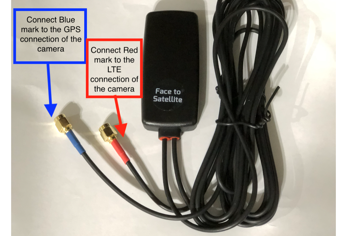
- CAUTION: The antenna must be mounted in an area which provides a clear view of the sky, and at least 8 inches away from the road facing device
- Note: The blue lead of the antenna is for GPS; the red lead of the antenna is for cellular (LTE)
- Prepare the windshield (similar to the step above) by cleaning the area intended for the antenna.
- Apply the double-sided backing tape to the side of the antenna labeled "Face to Satellite"
- Press the antenna to the windshield. Hold in place for at least 10 seconds.
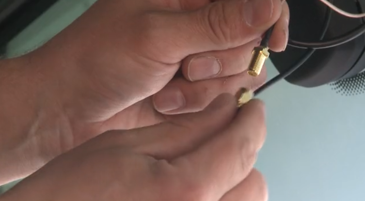
- Once mounted, connect the antenna cables to the camera
- Connect the red lead of the antenna to the connector on the camera labeled "LTE"
- Connect the blue lead of the antenna to the other connector on the camera
Wiring
CAUTION: Follow the steps below in order. Failure to do so may cause camera malfunction.
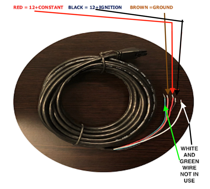
- Once inside the fuse panel, locate the ground, constant, and ignition source.
- Connect the brown ground wire to anywhere on the vehicle chassis
- Connect the red constant wire to the (included) red fuse holder
- Note: The constant wire should always have voltage, regardless of whether the vehicle is running or not. You can test the constant wire for voltage using a standard multimeter.
- Connect the black ignition wire to the (included) black fuse holder
- Note: The ignition wire should only have voltage when the vehicle is turned on. You can test the ignition wire for voltage using a standard multimeter, when the vehicle is turned on.
- Note: The white and green wires on the provided power cables can be disregarded and capped off.
(Optional) Using the View Monitor for video quality check
If using a monitor to check the view/position of the dual camera system, follow the steps below
- Plug the monitor into the brown fakra connector on the road-facing camera
- Power on the camera by turning on the vehicle ignition
- Once powered on, the monitor will only display the image of the road-facing camera lens
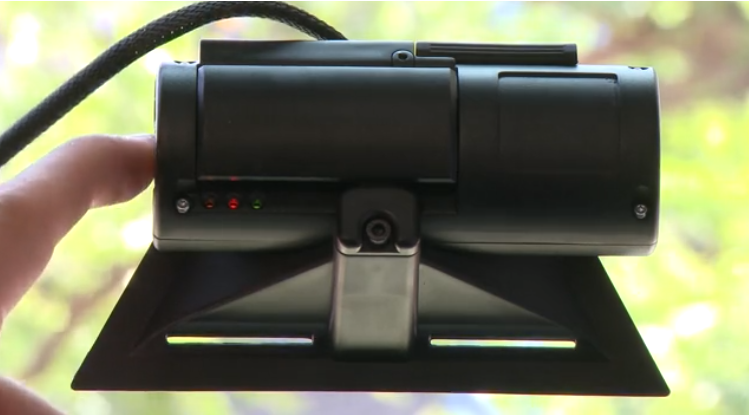
- After verifying that the image is good quality, press and hold the panic button (on the left side of the mounted road-facing camera) for 5-10 seconds, to view the image from the secondary ball camera lens
Device Calibration
CAUTION: To initiate calibration of the device, ensure your vehicle is outdoors with a clear view of the sky. Calibrating indoors may restrict GPS and/or cellular connectivity.
- Power on your camera by turning on the vehicle ignition.
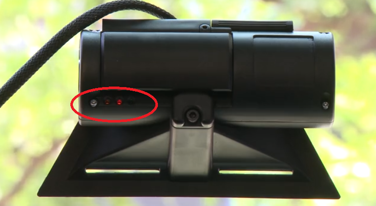
- Press and hold the camera's "panic" button (on the left side of the camera, next to the LED lights)
- The LED lights on your device will display a light sequence indicating its current state of connectivity. Once calibrated, the camera must read the following sequence:
- Solid orange LED (indicates GPS connection)
- Slow flashing red LED (indicates cellular connectivity)
- Solid green LED (indicates ready to record)
Note: It may take up to five minutes for your device to fully power on and flash in the correct LED sequence.
If the vehicle is outdoors and the appropriate light sequence is still not displayed after powering on the vehicle, please reach out to Support@SureCam.com or CustomerServiceUK@SureCam.com for troubleshooting assistance.
Remote Video Quality Check
Once the correct LED light sequence is established, keep the vehicle on and push the "panic" button (on the left side of the camera). This will trigger a short video clip which can be verified to complete the install.
Note: The green LED light will slowly flash indicating that the camera is transmitting the video.
Congratulations! Your connected camera is now installed and ready to go. For any additional questions, please reach out to Support@SureCam.com (for North America) or CustomerServiceUK@SureCam.com (for Rest of the World).